Electronic Fundamentals: Understanding Capacitors

Build a Digital Capacitance Meter
Background Theory of Capacitors
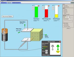
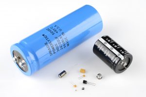
 Capacitors are one of the most common passive components in circuits just like the resistor. Capacitors store electrical charge and have different functions depending on the circuit design. The capacitance is a measure of how much charge or energy the capacitor can carry. In its most basic form, a capacitor consists of two conducting plates separated by an insulator (dielectric), which is commonly represented with its circuit design symbol. There are many different types of capacitors, made up of various dielectric material, used for many different purposes.
Capacitance is measured in Farads, which is a fairly large unit, so it is most generally used in microfarads (µF, 10-6) or picofarads (pF, 10-12). Capacitors can be either electrolytic or non-electrolytic. Non-electrolytic capacitors can be connected in a circuit in any direction. Electrolytic capacitors must be installed in the correct orientation on the circuit, as one lead is positive and the other negative. Placing electrolytic capacitors will incorrectly prevent your circuit from performing properly, or can even cause them to pop.
Capacitors have an array of applications. They play a critical role in digital electronics as they protect microchips from noise on the power signal by decoupling. Since they can dump their entire charge quickly, they are often used in flashes and lasers along with tuned circuit devices and capacitive sensing devices. Circuits with capacitors display frequency-dependent behavior, so they can be used with circuits that selectively amplify certain frequencies.
Capacitors can be added in series or parallel like resistors, but they are calculated the opposite of resistors. Components connected in series share one common node, and both nodes are shared when in parallel. Resistors in series are added together to find the total resistance, whereas capacitors connected in parallel are added together to find the total capacitance. Resistors in parallel and capacitors in series share the same formula to find the total value, Xeq = (1/[(1/X1+1/X2+…+1/Xn)], just substitute the resistor or capacitor value into X.
Check out how to decipher different types of capacitors, see our circuit notes on capacitors.
The Capacitor Project: Digital Capacitance Meter
This electronics project lets you measure capacitors in a range of capacitance from 0.000pF to 1000µF. That is, a 16×2 LCD Display will be displaying a scale from 0.000pF to 1000uF, whose main components will be an Arduino Uno and the display. If you lose the datasheet and need a quick measurement, this do it yourself project is perfect to perform a quick check.
Time Required: 10 hours depending on experience
Experience Level: Intermediate
Click here to Purchase Capacitance Meter Kit
Capacitance Meter Kit Includes:
| Component Name | Product No. | |
| 16×2 Character LCD Display – White on Blue 5V | DFR0063 | |
| Arduino Uno R3 DIP Edition (Revision 3) | A000066 | |
| Arduino Uno Proto Shield (PCB only) | A000082 | |
| 9V Battery Snap with 2.1mm Barrel Plug | 1X9V-2.1 SNAP | |
| Cable USB2.0 A/B 3 Feet Black USB-A Male To USB-B Male | 10U2-02203-BK | |
| Connector Unshrouded Header 40 Position 2.54mm Straight | 7000-1X40SG-R | |
| Potentiometer 1/4″ Square Cermet 1/2W 10KΩ | 3362P-1-103LF/76P103LF | |
| ABS Plastic Enclosure for Arduino Board – Fits UNO or MEGA | M000015 | |
| 6 Position Female Header – Pass through Style for Arduino | RS1-06-G-.561-A11596 |
Required tools and parts:
- Soldering iron
- Solder
- Wire strippers
- Cutter
- Needle nose pliers
- Multimeter
- Electrical drill
- Drill bit of 1/16″
- #22, wire any color, 1 meter
- A 9V battery
Step 1 – Schematic Diagram
In this step, you are going to concentrate very well in what you will be constructing. That is, this step of your project is crucial since you will need to understand how to connect each component so that the whole project functions correctly. Therefore, this step becomes the main step or an imperative measure so that your project be completed successfully. A larger version will be at the end of the instructions.

Click to enlarge
Step 2 – 16×2 LCD Display
In this step, you can cut 2×6 pins and put them into the holes of the16x2 LCD Display in the corresponding pins: 1 to 6 & 11 to 16 so that you can have more space for working between the PCB and the Display when this last one be installed.

Step 3 – 16×2 LCD Display 2
In this step, you are going to do the main connections to the display that you will connect to your Arduino Uno later. Then, you should identify the connections from 16×2 LCD Display in the pins: 4, 6, 11, 12, 13, and 14 that will be connected respectively to the Arduino Uno in the pins: 11, 9, 5, 4, 3, and 2 without forgetting the connections to +5V, GND, and Pot of 10K.

Step 4 – 16×2 LCD Display 3
In this step, you are going to match the connections done previously to your LCD Display with the future connections that you will do in the PCB: observe the photo where you can see the details closer.

Step 5 – PCB
Once you know how to do the connections between your 16×2 LCD Display and the PCB, you should separate them so that you can install on the PCB: the Connector Unshrouded Headers by utilizing 2×8 pins in the side of the digital pins while using 2 pins in the other side for connecting to GND and +5V.

Step 6 – PCB Connections
In this step, you are going to connect the GND’s so that you can have all GND’s connected and so you can install the pot of 10K directly on the GND track and then you can connect it to +5V track as well while completing the connections to this component soldering the central pin to other close track.

Step 7 – PCB 3
Now, you can do all of connections: that is, preparing the connections and leaving enough space so that can later install the 16×2 LCD Display.

Step 8 – Joining the PCB & the Display
It’s time to match each connection between the PCB and your LCD display so that can later solder correctly each element installed.

Step 9 – Joining the PCB & the Display 2
Check carefully the connections in the back side of your PCB so that you can observe if everything is OK with those connections that you did between the PCB and the LCD Display. Obviously, you are going to check the connections done to GND and +5V on the right track as well.

Step 10 – Completing the Project
Once completed the project, leave clear which the outputs are. That is, it’s imperative to define the outputs for this project: in this case, they are A0 for the negative (-) and A4 for the positive (+).

Step 11 – Getting Ready For Doing Precision Measures
Before uploading the code, you should eliminate the metallic parts of the PCB’s holes of A0 and A4 using a drill bit of 1/16″ in order to keep ‘0’ (zero) capacitance when the 1×6 Position Female Header – Pass through Style for Arduino Uno is installed.

Step 12 – Arduino Enclosure
Before installing the Arduino Uno in its enclosure, cut the plastic posts.

Step 13 – Mounting the Shield on the Arduino Uno
Once installed the Arduino Uno inside the enclosure, you can mount the shield on the Arduino Uno.

Step 14 – Inserting the 1×6 Position Female Header – Pass through Style for Arduino
In this step, you can insert the 1×6 Position Female Header – Pass through Style for Arduino Uno and so when you upload the code then the cursor will display 0.000pF.
Step 15 – Uploading the Code
Pluging the USB-A to USB-B cable between your project and the computer, upload the code at: http://pastebin.com/njjKZrfv
Next, observe the cursor where you will see 0.000pF.

Step 16 – Using Capacitance Meter
Once uploaded the code from http://pastebin.com/njjKZrfv , unplug the USB-A to USB-B cable that is plugged between the computer and your project so that you can plug your 9V Battery Snap with 2.1mm Barrel Plug and so can also use your 9V battery to get the measure of each capacitor what you want to measure. In this case, I am measuring a 1 pF capacitor. Note that before measuring the capacitor, you can observe in the cursor: 0.000 pF.
Step 17 – Measuring a Capacitor of 10nF

Step 18 – Measuring a Capacitor of 10pF

Step 19 – Measuring a Capacitor of 3.3pF